Monday 29 May 2023

UPDATED : North Korea announces satellite launch for May 30 - June 10

UPDATED 29 May 2023 12:00 UTC to reflect alternative orbit option

UPDATED 30 May 7:45 UTC to add comparison with 2016 launch 

UPDATE 30 May 22:00 UTC: the launch seems to have happened, around 21:30 UTC (May 30)

UPDATE 31 May: the launch reportedly failed early in flight due to a problem with the 2nd stage

(this post has been updated several times, with new pargraphs added, following development of the case. Newest paragraphs are near the bottom of the post)


According to South Korean media
, North Korea has informed Japan that they will launch a satellite between May 31 and June 11. Navigational Warnings have appeared that suggest a launch in this period as well.

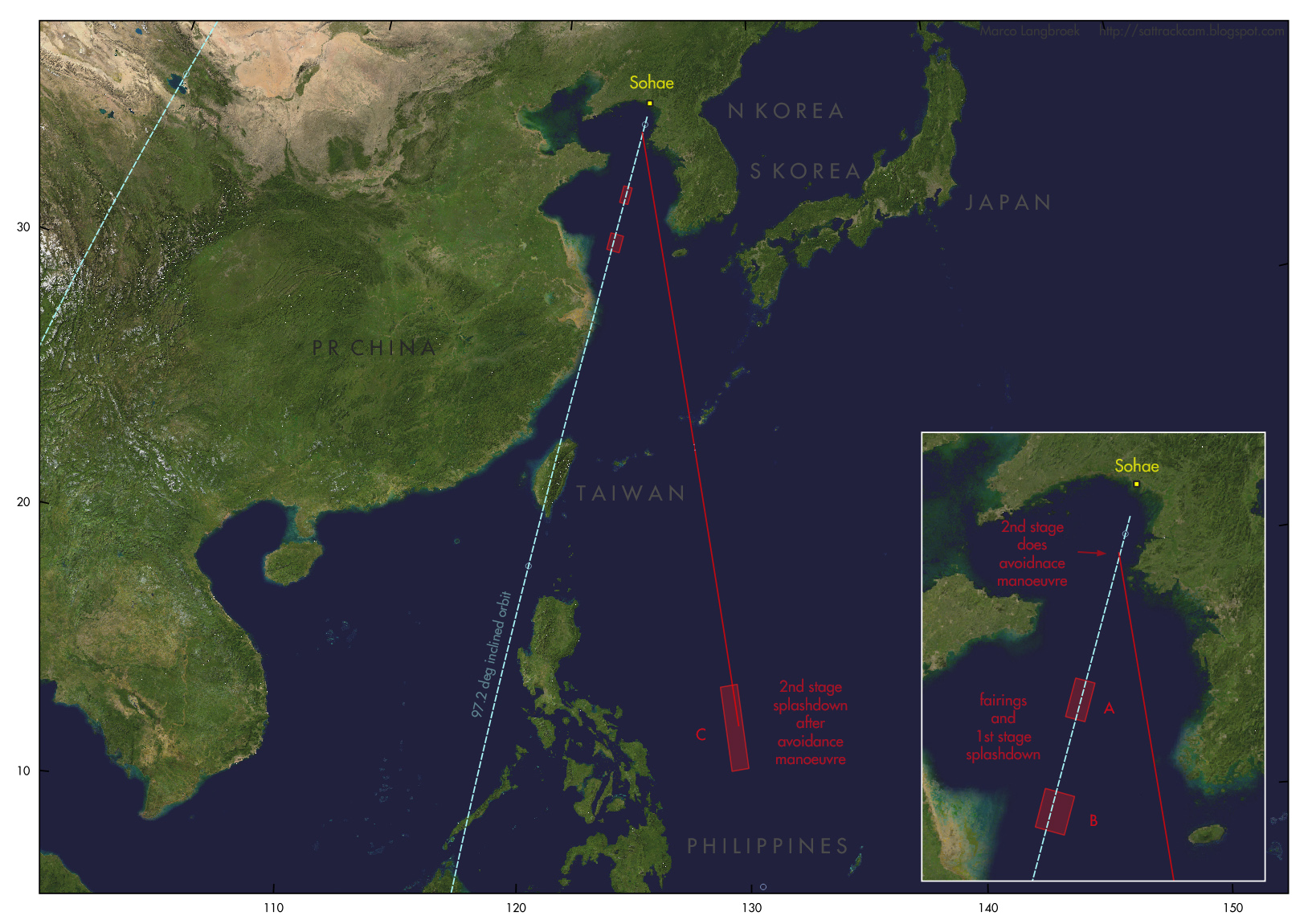
Navigational Warning HYDROPAC 1779/23 (see below) gives three hazard zones, the first two of which line up with the Korean launch site Sohae. Below is the text of the Navigational Warning in question, and a map where I have plotted the three hazard zones A, B and C and the approximate launch trajectory I reconstruct from these (numbers next to the trajectory indicate minutes after launch):
[UPDATE: but see alternative option near bottom of post, that I am increasingly inclined to]

click map to enlarge

282008Z MAY 23
HYDROPAC 1779/23(91,92,94).
EAST CHINA SEA.
PHILIPPINE SEA.
YELLOW SEA.
DNC 11, DNC 23.
1. HAZARDOUS OPERATIONS, ROCKET LAUNCHING
   301500Z MAY TO 101500Z JUN
   IN AREAS BOUNDED BY:
   A. 36-06.56N 123-33.07E, 35-24.31N 123-22.47E,
      35-20.01N 123-48.37E, 36-02.26N 123-59.11E.
   B. 34-05.54N 123-01.59E, 33-23.28N 122-51.53E,
      33-16.32N 123-29.40E, 33-58.58N 123-40.04E.
   C. 14-54.10N 128-40.06E, 11-19.18N 129-10.50E,
      11-26.49N 129-54.08E, 15-01.42N 129-24.03E.
2. CANCEL THIS MSG 101600Z JUN 23.


Note that May 30, 15:00 UTC corresponds to May 31, 00:00 local date/time in North korea, and June 10, 15:00 UTC to June 11, 00:00 local date/time. So the window of the Navigational Warning, in local North Korean date/time, matches that given by North Korea.

click map to enlarge

Areas A and B between China and Korea are likely the splashdown zones for the first stage and fairings, area C east of the Philippines is the splash-down zone for the second stage. Their relative locations point to a dog-leg manoeuver just after launch, after first stage separation and fairing ejection. First stage and fairing continue on the original launch course untill splashdown, the second and third stage, after the dogleg, insert the payload into a ~78 degree (give or take a degree or two)  inclined orbit.

The orbit is NOT sun-synchronous. It is different in orbital inclination than the orbits of the previous North Korean satellite launches: KMS (Kwangmyŏngsŏng) 3-2 and KMS 4, which are in 97.2-97.3 degree inclined orbits.


UPDATE (29 May 2023 12:00 UTC)

It was deep into the night when I originally wrote this blogpost. After a night's sleep and a discussion with Bob Christy, I am inclined towards another solution: direct insertion into a 97.2 degree inclined sun-synchronous orbit, followed by an avoidance manoeuvre of the 2nd stage after 3rd stage separation to avoid the 2nd stage falling on the Philippines:


click map to enlarge

click  map to enlarge

The location of areas A and B would fit well with this scenario. The risky part is that it means an overflight of the coastal PRC and Taiwan early in the launch trajectory. If something goes awry, this could result in hardware coming down on the PRC, Taiwan of Philippines nevertheless.

Yet this option is more and more enticing to me. The resulting orbit would be sun-synchronous, i.e. fitting an optical reconnaissance satellite, and similar to the orbits of KMS 3-2 and KMS 4. The scenario to arrive there however differs from the 2012 and 2016 launches. Here initial launch direction is into the intended orbital plane and the 2nd stage is doing a post-separation avoidance manoeuvre; whereas in 2012 and 2016, the initial launch direction was different and the 3rd stage did a manoeuver and pushed the payloads into the final orbit. The post-separation avoidance manoeuver of the 2nd stage in the current scenario would point to a (new) re-startable 2nd stage, which is interesting

The 2nd stage will splash down into a very deep part (5.7 km) of the Pacific Ocean, which makes recovery very challenging. This could be another reason why they divert it into this direction. It could be an indication that the 2nd stage is something new that they don't want to fall into the wrong hands.

If the launch is done at similar solar elevations as in 2012 and 2016, we can expect launch near 21:50-21:55 UTC, about 1.5 hours after sunrise at Sohae.

The intended orbital altitude is probably near 500 km.

Below is a very rough orbit estimate for launch at 21:50 UTC on the first available date (May 31 6:00 local time in N Korea is May 30 in UTC):


KMS 5                          for launch on 30 May 2023 21:50:00 UTC
1 70000U 23999A   23150.90972222  .00000000  00000-0  00000-0 0    06
2 70000 097.2299 155.8806 0003636 152.0900 325.4205 15.22766913    08

UPDATE (30 May 22:00 UTC):

Launch seems to have been near 21:30 UTC. here is an orbit estimate, assuming direct insertion into SSO, for launch at 21:30 UTC:

KMS 5                          for launch on 30 May 2023 21:30:00 UTC
1 70001U 23999A   23150.89583333  .00000000  00000-0  00000-0 0    06
2 70001 097.2299 150.8669 0003636 152.0900 325.4205 15.22766913    01


UPDATE 30 May 2023, 7:45 UTC:

In the map below I have depicted the location of the hazard zones and (initial) launch directions for the launch of KMS-4 in 2016 (blue), and the upcoming launch (red). Note the difference in (initial) launch direction between 2016 and now, and the odd off-set chacater of area C for the current launch:

click map to enlarge


In 2016, it was the third stage that did a dog-leg to get the payload into a 97.2 deg inclined Sun-synchronous orbit. The initial launch trajectory was probably selected to minimize risk of the 1st stage falling on the PRC and the second stage falling on the Philippines:

click map to enlarge

It is very clear that the upocoming launch will be according to a different scenario than the 2016 KMS-4 launch. Something odd is happening with the second stage, clearly.


UPDATE 31 May 2023: LAUNCH FAILED TO REACH ORBIT

The launch failed in flight, according to the North Korean State News Agency KCNA due to a problem with the 2nd stage. The KCNA news  report provides a launch time of 6:27 North Korean time (21:27 UTC May 30). It mentions that the launch was with a new type of carrier rocket, "Chollima-1", and gives the name of the failed satellite as "Malligyong-1".

It says that the failure was due to "losing thrust due to the abnormal starting of the second-stage engine after the separation of the first stage during the normal flight".

Yonhap reports the crash site as "200 km west" of the island of Eocheongdo. That matches well with area A, the first stage splash-down zone, from the Navigational Warnings (see map below). If the second stage failed to ignite, both the first stage and the second/third stage plus payload stack could have ended up here.

One of the stages has been recovered by South Korea, presumably from this area (photo's in this tweet thread). It seems quite intact and could be the spent first stage.

click map to enlarge

North Korea recently released images of the payload during factory testing, and already hinted at a nearby launch (see previous post here).


image: KCNA

Wednesday 17 May 2023

Gearing up for a new North Korean satellite launch

photo: KCNA

On May 17, the North Korean News Agency KCNA and the North Korean State Newspaper Rodong Sinmun carried a news item, accompanied by photographs, of Kim Jung Un and his daughter Kim Ju Ae inspecting a new North Korean satellite in its assembly facility.

Photographs show a satellite purportedly undergoing testing. It is identified in the news items as military reconnaissance satellite no. 1, said to be "at the final stage" and "ready for loading after undergoing the final general assembly check and space environment test".

The satellite looks superficially similar to Kwangmyŏngsŏng-3 (KMS-3).  It is an oblong box with what looks to be hinged, deployable solar panels on two of its four sides. 

The satellite has been blurred on the imagery. What appears to be sensors can nevertheless be seen, albeit blurred (and perhaps the images might be in other ways manipulated).

My cautious estimate is that the satellite measures approximately 1.5 x 1.2 x 0.6 meter.


photo: KCNA

photo: KCNA

photo: KCNA

Protrusions that could be sensors can be seen, on the top and on the sides. Here are some very cautious interpretations (and I am open to other suggestions) of the blurred imagery details:

possible sensors on top (interpretation)

possible sensors on side (interpretation)


The most likely launch site will be Sohae (39.66N, 124.70 E), where previously KMS 3-2 and KMS 4 were launched from. Sohae has seen intermittent construction works the past year.

In April, North Korean State Media already announced that the country was at the verge of a reconnaissance satellite launch. Components purportedly have been tested as part of recent missile test launches, some of which featured remote sensing imagery.

This new KCNA report of Kim Jung Un visiting the test/assembly facility, is another sign that a satellite launch is probably not too far off in the future.

Most likely the satellite will be launched into a ~97 degree inclined sun-synchronous polar orbit at roughly 500 km altitude, as KMS 3-2 and KMS 4 were. KMS 3-2 and KMS 4 were launched with UNHA-3 rockets: perhaps this new satellite will be as well.

The imagery below, which I shot in September 2018, shows North Korea's satellite KMS-4 (Kwangmyŏngsŏng-4), which was launched in February 2016 and was their last satellite launch:

Sunday 7 May 2023

Calibrating tracking astrometry accuracies using SWARM as calibration objects

Artist impression of SWARM (image: ESA)


When I started tracking satellites and publishing this blog 18 years ago, I spent a lot of time on validating the accuracy of my methods and observations. A lot has happened since then: I moved on to better equipment, and new validation methods have become available.

In this blogpost, I revisit the accuracy of my current video observations, using ESA's SWARM satellites as calibration targets.

The SWARM satellites (2013-067A, B and C) are well suited for system validation. Accurate GNSS-fit based orbital positions with centimeter accuracy are publicly available for these satellites, which means there is a firm reference to compare to. And the SWARM satellites are quite bright, hence they are relatively easy to observe (the video below shows a pass of SWARM A on 27 March 2023, imaged with a 85 mm lens).


Observations, equipment and methods

From the last week of March 2023 to the 3rd week of April 2023, I targetted SWARM A and B while they were making a series of well-observable passes over Leiden. 

There were two reasons for this endeavour. One was the creation of a good tracking dataset with known 'ground truth" for our research at Delft Technical University, where a colleague is working on improved methods of orbit determination from optical observations. The second was, that such observations provide you with information on the astrometric accuracy of various camera/lens combinations. 

My previous endeavours to gain insight into the accuracy of my observational data were based on comparisons of observations to TLE's. True vector positions from fitting to data from GNSS receivers onboard the satellite(s) are however much more suited for this than TLE's, as they are much more accurate (to cm-level, whereas those of a TLE are to km level).

The equipment I used to obtain the data presented in this blogpost was a WATEC 902H2 Supreme camera with a GPSBOXSPRITE-2 GPS time inserter, and three lenses: a Pentax 1.2/50 mm, a Samyang 1.4/85 mm and a Samyang 2.0/135 mm. Astrometry on the imagery was done on a frame-by-frame basis using Hristo Pavlov's TANGRA software.


WATEC 902H2 Supreme camera with Pentax 1.2/50 mm lens and GPS time inserter

same camera as above but with 2.0/135 mm lens


The camera films at 25 frames/second. The PAL video signal is fed into the GPS time inserter, which imprints each frame with a millisecond-accuracy time marking. The signal is then fed into an EZcap digitizing dongle and recorded on a laptop, after which astrometry is done on the files with TANGRA, on a frame-by-frame basis.

Observations were done on 8 separate nights in the period 27 March-19 April 2023. 1544 datapoints from 3 separate passes were obtained with the 50 mm lens; another 4100 datapoints from 5 separate passes with the 85 mm lens; and 891 datapoints from 3 separate passes with the 135 mm lens.

In addition to this, Cees Bassa and Eelke Visser both provided a set of data from their video systems. This allowed to explore any differences between their equipment and mine.

Cees and Eelke use USB connected ZWO ASI camera's with a CMOS sensor. Cees' camera is a ZWO ASI 1600 MM with a 1.4/85 mm lens; and Eelke's camera is a ZWO ASI 174MM with a 1.4/50 mm lens. 

Their timings come from the PC clock which is synchronized through NTP. Their astrometry is done using Cees' STVID software. As we will see later, there are some clear differences in accuracy between their systems and my system.


Reference positions

I wrote a software program, "Vect2RADEC', that converts SWARM navigational positions (ITRF X Y Z coordinates) to J2000 RA and DEC positions as seen from the camera location, and optionally also calculates residuals with astrometrical positions if you provide a file with the latter. The software is available in the software section of my website at http://software.langbroek.org (64-bits Windows only).


Results (1)

First, results for my own system using various lenses. Below are error distribution plots for the three lenses used: plotted is the distribution of the distance delta (in arcseconds) between the astrometrically measured, and actual GNSS derived position.

The first plot is a combined plot, followed by plots per lens. The average accuracy, and the one sigma standard deviation on this, is listed in the plots as well.

combined plot of error distributions


For each lens, the average accuracy is clearly better than the one-pixel resolution of the camera/lens combo in question. These pixel resolutions are resp: 

1 pixel = 35.4"  for the 50 mm  lens; 

1 pixel = 20.9"  for the 85 mm lens;

1 pixel = 13.1"  for the 135 mm lens. 

The actual astrometric accuracies are at about 2/3rd of this, i.e. astrometric positions are accurate to sub-pixel level.

The error distribition for the 50 mm lens is a normal distribution. Those for the 85 mm and 135 mm lens are increasingly skewed, showing a tail towards lower accuracies in their error distributions.

The tails to lower accuracy in the plots for the 85 mm and 135 mm lens are caused by trailing of the satellite in individual frames: at the resolutions of these lenses, trailing becomes apparent at shorter range to the camera. TANGRA does not center well on trails, the software is meant to fit on point-like objects.

The dependency of accuracy on range for the various lenses as a result of trailing  is visible in these plots of error against range:


At the resolution of the 50 mm lens, trailing is not much of an an issue, even at minimum range: the error is constant. With the 85 mm lens, trailing (with a corresponding drop in accuracy) starts once the range is less than ~725 km. With the 135 mm lens, it starts as soon as the range is less than ~1200 km.

The following diagrams show the corresponding trends in actual error in meters at satellite range (perpendicular to the viewing direction), for the three lenses:


Results (2)

As a second investigation, it was interesting to compare the performance of my system to that used by Cees Bassa and Eelke Visser, who graciously made data available to me for this purpose. 

In the diagram below, the distribution of residuals from Cees' system (green) is compared to those for my system (blue) for the same lens, a 1.4/85 mm Samyang lens.  Cees' data (with a much lower number of individual datapoints) have been scaled on the Y-axis to visually match mine, in order to make the visual comparison of both distributions more easy.


What is immediately apparent is the difference in accuracy. The average error in Cees' results in a factor 6 worse than mine, and the distribution spreads much wider as well. It is also a factor 5 worse than the pixel resolution of his camera (whereas mine is at 2/3rd of the pixel resolution). Eelke's data, not visualized here, show a similar pattern.

The software which I wrote to assess these errors, currently does not differentiate between along-track ("delta T") and cross-track errors. A comparison of Cees' and my data against a TLE using Scott Campbell's SatFit software, which does differentiate between delta T and cross-track error (but only to two decimals behind the dot, in degrees and time), suggests that much of the difference in error actually stems from a larger along-track error, i.e. an error in the timing, in Cees' data.

This could have a couple of causes. One or more of these factors could be in play here:

(1) an uncorrected latency introduced by Cees' camera system;

(2) a latency introduced by the pc clock-to-STVID throughput of times

(3) a residual latency in the NTP time source

(4) the frame exposure mid-time registered by STVID might actually be the start- or end-time of the frames

(5) the frame stacking method used by STVID

NOTE: It should be explicitly remarked here that Cees never designed his system and software with the kind of precise accuracies in mind that we are mapping here

In our independent tracking network focussing on orbit determination of classified objects, we generally are happy if positions reported are accurate to 2 arcminutes, rather than a few arcseconds. This is because of two reasons:

(a) The goal is to create TLE's for orbit characterization and overflight predictions for these objects. TLE's have an intrinsic accuracy of 1 km (and worse away from epoch time) in position, so a 2 arcminute accuracy in positional determinations is sufficient for this goal.

(b) Positional data of varying quality obtained by various different methods are lumped in the orbit determinations by our independent network analysts. These include: visual observations with binoculars and stopwatch; camera still images; video data with astrometry on either stacked frames or individual frames; with timing sources varying from stopwatch synchronization to radio "six pips", DCF77 radio-controlled clocks, to software synchronization to NTP time synchronization, to GPS time inserters. 


NOTE ADDED 9 and 10 May 2023:

In a discussion on Twitter, the issue of light travel time was raised. I have come to the conclusion that this is almost certainly already included in the AFSPC-origin libraries I use for my software (even though not explicitly documented for the conversion of ECI position to RA/DEC as seen from the station, it is documented for another conversion, so likely to be incorporated in the former as well), for as I try to include my own additional correction, this actually makes the residuals worse.


Acknowledgement: I thank Cees Bassa and Eelke Visser for providing comparison data from their systems.